The recent dramatic — nearly an order of magnitude — resource downgrade of a high-profile deposit has sparked lively discussions amongst geology professionals.
Many geologists are discussing the technicalities of the resource estimation, such as geostatistical checks and balances, and the premature decisions made by the mining company, but I’ll focus on one simple issue, which no one has raised, that can easily result in an order of magnitude resource downgrade under specific situations.
I’m referring to the tabular orebody modelling process, which has been around for decades. Used appropriately, it is a perfectly fine method, but a problem occurs when the vertical sections used to interpret tabular continuity are not orthogonal to the expected maximum grade continuity axis of a deposit.
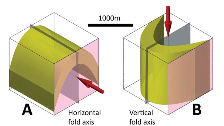
The above figure shows on the left a model of an upright fold that is mineralized (A). The red arrow points along the first-order maximum horizontal grade continuity that is expected from this fold geometry.
As exploration geologists, if we recognize folding, we would place our drill hole fences parallel to the fold profile (the planar orientation shown in pink). This profile section is orthogonal to the maximum continuity of grade — serial sections parallel to this orientation will help us model grade continuities by simply drawing on these multiple serial sections and connecting them. In this situation, the continuity of high grades may be tabular locally, and parallel to bedding and the axial planar cleavage.
However, the most important grade continuity would be linear high-grade shoots, parallel to the bedding-cleavage intersection line. These shoots can occur as cigar-shaped geometries, or when many planar veins intersect that share a common intersection line along the fold axis.
The fold on the right (B) is exactly the same fold, but rotated to a vertical plunge. In this case, the longest expected grade continuity is vertical, as shown by the arrow. Again, the best section to use for interpretation would be orthogonal to the continuity direction, which is the horizontal fold profile plane.
However, in real life, the drill fences are vertical. So geologists use vertical sections as their primary interpretation planes, instead of horizontal.
Decades of habit mean that geologists place more weight on interpreting vertical sections that are parallel to the drilling than on any other section. An example of such a vertical sectional plane — assumed to be parallel to the drill fences — is shown in pink on fold B.
This section may be optimal for viewing the drilling data, but it is not optimal relative to the structural architecture, and it is almost uninterpretable in terms of grade continuity. If tabular grade continuity is assumed to connect out of this plane, expect problems — the true long-range continuity is parallel to the arrow and to the sections you are using for interpretation, and is not orthogonal.
You may see a perfectly continuous trace of grade in one section (incorrectly assuming that it’s part of a tabular zone), but the grade continuity will completely disappear in the sections on either side!
Only a determined geologist will persist with tabular modelling using these sections, making tabular resource wireframes that contravene the expected grade continuities — geometries that could have been simply predicted from the structural architecture.
For multi-folded host lithologies, the situation is more complex, but still decipherable. An earlier deformation may impose a strong lithological continuity, which may be oblique to the grade continuity.
If you use vertical sections for modelling lithology, you have to show that the lithological continuity is horizontal.
If a later grade event is oblique to the stronger lithological continuity, it isn’t logical to use the lithological continuity to predict grade continuity. These are separate events — you must clearly distinguish them, and determine appropriate modelling methods separately for each.
Unfortunately, “tabular geometry modelling using vertical sections” is nothing more than dogma burned into the heads of most geologists, due to decades of habitual sectional digitization.
Because of this, it is used inappropriately in many situations. Equally unfortunately, software used by geologists tends to emphasize how quickly tabular bodies can be modelled, without cautioning users in the specifics of how, or even if, this method should be used.
Leapfrog Geo’s tabular vein modelling workflow allows geologists to rapidly model tabular zones without any checks and balances written into the process, and without incorporating structural intelligence.
Inexperienced geologists, particularly those who lack field experience in structural geology, will happily model tabular zones of mineralization without ever considering what is realistically possible.
This practice of using inappropriate vertical sections can easily lead to an order of magnitude resource downgrade, especially if you mine an assumed tabular deposit that was built using these sections.
This is not a complex issue. There’s no need use geostatistical software to make dozens of experimental variograms to understand the expected grade patterns, when you can predict it from the structural architecture. If the geology appears “complex” and grades don’t seem to connect horizontally, maybe you’re using the wrong view to interpret your geology. If that’s the case, the grades will never connect along that direction.
What the grades should do should be obvious from the structural architecture. The above illustrations of folds, and their expected continuity of mineralization, can be understood by a second-year geology student who has had some structural geological education.
Not all vertical sections are created equal, and it is up to the geologist to determine what sectional orientations are appropriate for resource modelling.
I recommend that you:
1) Document the structural geology at the deposit scale. There’s no need to collect thousands of foliation measurements and hire expensive structural geology consultants — simply work out the structural architecture of the deposit at the first-order deposit scale using the data you already have. I have outlined a quick and accurate method in a link available at www.orefind.com, but if you’re still stuck, contact me.
2) Let the structural architecture guide the resource modelling process. There is no point in finding out the structural architecture if you’re not going to convert that knowledge into expected grade continuities at the deposit scale, and then use that information during resource estimation.
Fewer resource downgrades will occur if attention is paid to the orientations of sections that are used for tabular orebody modelling.
(Author’s disclaimer: The above characterization of a deposit is fictional and for illustration purposes only.)
— E. Jun Cowan, PhD, is a director and principal structural geologist of consulting firm Orefind, and the conceptual founder of Leapfrog geological modelling software. He holds an adjunct senior research fellow position at the School of Geosciences, Monash University.
Based in Fremantle, Western Australia, Orefind is a geological consulting company founded by structural geologists Brett Davis and Jun Cowan.
Please visit www.orefind.com for more information and to read the company blog, where this article first appeared with detailed references to key articles.


Be the first to comment on "Commentary: A recipe for shrinking a mineral resource by 90%"